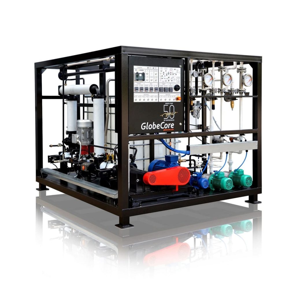
The UVB-1 productivity of 2 m3 per hour

UVB-1 bitumen unit is designed for production both anionic and cationic bitumen emulsions, which are used in road construction as follows:

  • base coat on old road top before application of asphalt-concrete;
  • preparation of cold asphalt concrete mixes;
  • surface treatment of road top;
  • thin film protective coats;
  • patch repair of roads etc.

The unit is designed for operation at asphalt concrete production facilities. It can be operated either outdoors under canopy or indoors.

SPECIFICATIONS

Parameter

Value

1 Max production capacity (including preparation time), m3/hour

3,5*

2 Bitumen consumption (90…130 penetration), minimum, m3/hour

1,5

3 Water consumption, m3/hour

0,6…1,5*

4 Flux consumption (if bitumen penetration below 90), dm3/hour

0…50*

5 Acid consumption, dm3/hour

5…20*

6 Emulsifier consumption, dm3/hour

5…20*

7 Adhesion additive consumption, dm3/hour

1…20*

8 Max bitumen input pressure, MPa

0,2

9 Bitumen to mixer pressure, MPa

1,4…1,6

10 Water phase to mixer pressure, MPa

0,2

11 Bitumen input temperature, 0С

140-160

12 Water input temperature, 0С

40-60*

13 Emulsion head after unit, meters, max

15

14 Max nominal power, kW

17

15 Power voltage at 50 Hz AC, V

380

16 Compressed air pressure, bar

4…6

17 Air consumption, dm3/minute

250

18 Dimensions, mm:

     -length

2510

     -width

1720

     -height

1820

19 Weight, kg

1700

* Depends on production recipe!

UVB-1 water-bitumen unit is semi-automatic, all components are mounted on a single frame and are interconnected by pipelines.

UVB-12

UVB-1 general view

The frame of the unit supports the following components:

  • bitumen reverse pump;
  • flux supply pump;
  • emulsion mill;
  • blend pump;
  • water pump;
  • bitumen supply valve;
  • flux supply valve;
  • water phase supply valve;
  • blend supply valve;
  • water flow meter;
  • blend flow meter;
  • flux flow meter;
  •  bitumen and flux mixer;
  • bitumen and water phase mixer;
  • emulsion and latex mixer;
  • water phase mixer;
  • blend mixer;
  • flux safety valve;
  • emulsion safety valve;
  • flux adjustment valve;
  • blend adjustment valve;
  • water adjustment valve;
  • acid consumption tanks;
  • emulsifier consumption tanks;
  • additive consumption tanks;
  • air preparation assembly.

Water pipeline is equipped with a mesh filter.
Flux pipeline is equipped with mesh filter.
Manual valves are also installed on pipelines.
The heating system is equipped with valves:

  • input;
  • output.

The unit is equipped with temperature and pressure sensors.
Water temperature is measured at the following points:

  • water supply;
  • blend supply;
  • bitumen to unit supply;
  • bitumen to mixer supply;
  • emulsion output;

Pressure is measured at following points:

  • before unit;
  • after bitumen pump.

The unit is supplied with emulsion tank heater.

The heater is a welded flat platform. A 200 liter emulsifier barrel is placed on the platform. A heating agent circulates through pipes in the platform.

The control panel is an air-tight metal case containing «Schneider zelio» controller, Autonics measuring regulators, protection and start equipment

 control_panel

Pos

Item

Pos

Item

1

Controller

14

K4 “Blend” valve switch

2

Diagram

15

Kerosene “Flux” switch (for automatic mode)

3

Indication of bitumen temperature before the pump “T1 temperature”

16

Lights test button

4

Indication of bitumen pressure before the pump “P1 pressure”

17

Emergency stop button

5

Indication of bitumen temperature after the pump “T2 temperature”

18

M1 pump “Bitumen forward” control double button

6

Indication of bitumen pressure after the pump “P2 pressure”

19

M1 pump “Bitumen reverse” control double button

7

Indication of emulsion temperature before the mill “T3 temperature”

20

Mill C4 control button

8

Indication of emulsion pressure before the mill “P3 pressure”

21

M3 pump “Water” control double button

9

Indication of water temperature “T4 water temperature”

22

M4 pump “Blend” control double button

10

Manual phase breaker

23

M5 pump “Flux” control double button

11

K1 valve switch “Bitumen”

24

Automatic mode “Start” button

12

K2 valve switch “Solution”

25

Mode selector switch

13

K3 valve switch “Flux”

26

Automatic mode “Stop” button

27

Indication of blend temperature “T5 blend temperature”

UVB-1-2_shema

Typical equipment placement diagram for bitumen emulsion production site

No

ITEM

AMOUNT

1.

Emulsion preparation unit

1

2.

Acid storage tank

1

3.

Bitumen boiler

1

4.

Bitumen pump assembly

1

5.

Water storage tank

1

6.

Water pump assembly

1

7.

Flux storage tank

1

8.

Emulsion storage tank

1

9.

Emulsion pump assembly

1

10.

Additive tank

1

11.

Emulsifier tank

1

12.

Oil heating station

1

13.

Compressor

1

14.

Bitumen filter

1

UVB-1

UVB-1 in manufacture

    GlobeCore

    LEAVE A MESSAGE